USD
USD
Mitsubishi M70 CNC resonance adjustment method
Mitsubishi M70 system resonance adjustment method
"Diagnosis----Drive Monitoring" screen:
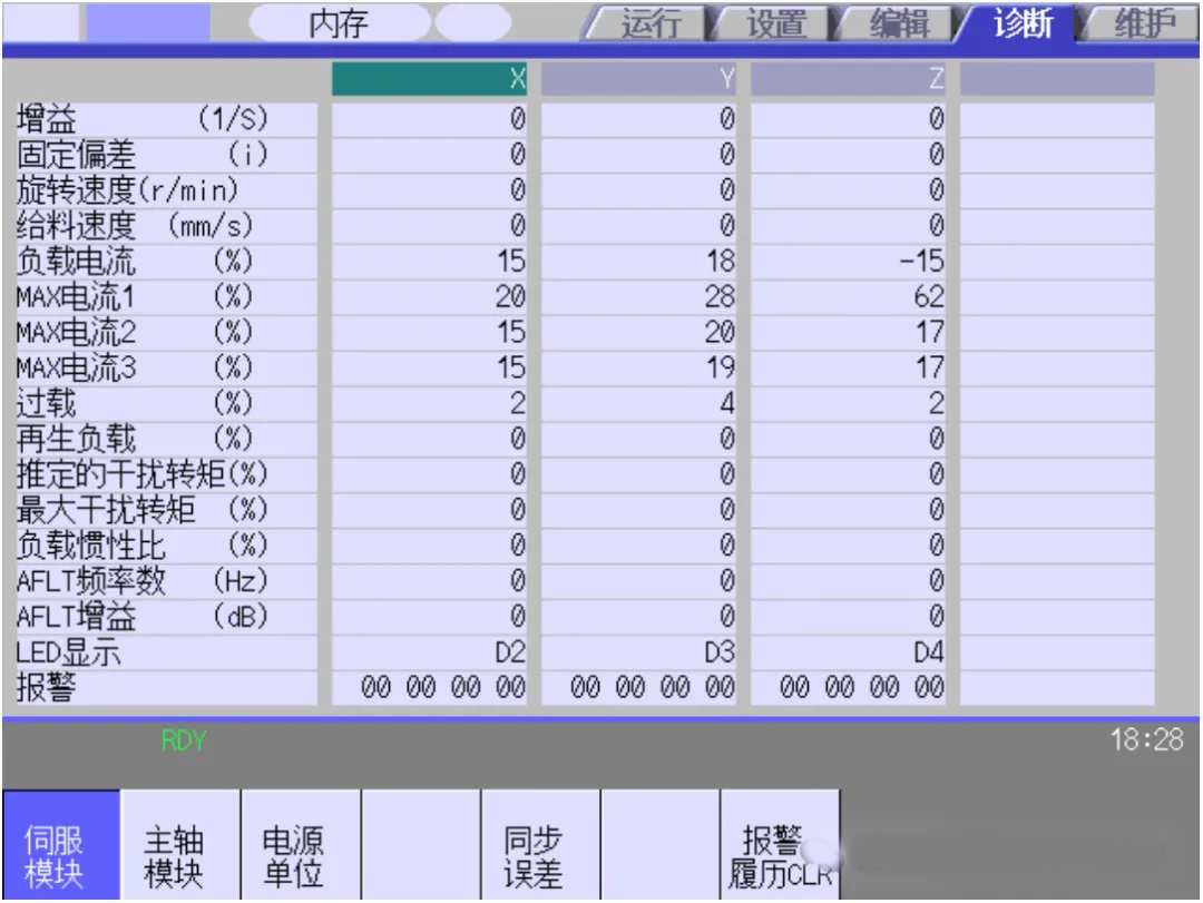
1. Resonance adjustment
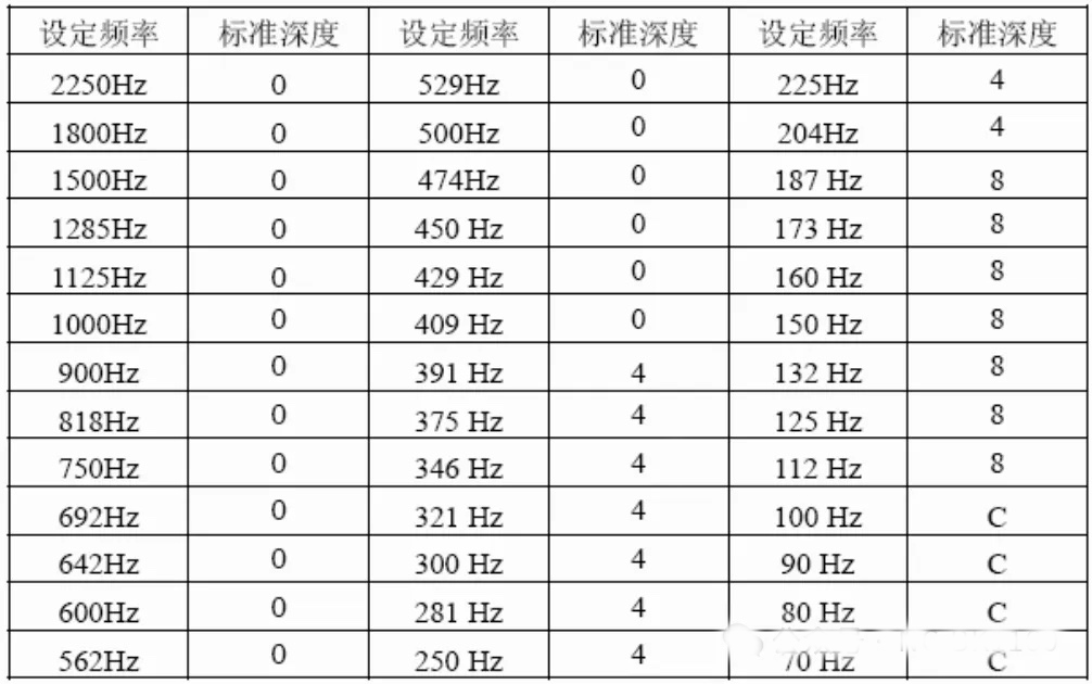
(1) Continue to increase the speed loop gain until resonance occurs. Lower the speed loop gain at this time slightly as the value of #2205, then move the axis, and adjust the frequency according to the "AFLT frequency number" on the "Diagnosis----Drive Monitoring" screen. "Get the resonance frequency, check the table below, enter the obtained resonance frequency value into #2238, and then move the axis. If there is still resonance, enter the obtained second resonance frequency value into #2246. Use #2233 to adjust the depth of resonance suppression.
For example:
Measured value:
(1)#2238--235 #2246—396
Check the table to get the actual setting values: #2238-225, the depth is 4; #2246-391, the depth is 4, then #2233-0044.
(2) If the second resonance frequency value is 0, that is #2238—235 #2246—0
Check the table to get the actual setting value: #2238-225, the depth is 4, corresponding to the second resonance frequency, then set the depth parameter SV033 to 0040.
2. Load inertia ratio adjustment
(1) Set #2235 to 8000, move the axis at 100% rapid traverse speed, observe the "Load Inertia Ratio" on the "Diagnosis - Drive Monitoring" screen, and enter the obtained average value into #2237. After the setting is completed, set #2235 back to 0000.
(2) Recommended values: #2243--100, #2244---100.
"Diagnosis----Drive Monitoring" screen:
1. Resonance adjustment
(1) Continue to increase the speed loop gain until resonance occurs. Lower the speed loop gain at this time slightly as the value of #2205, then move the axis, and adjust the frequency according to the "AFLT frequency number" on the "Diagnosis----Drive Monitoring" screen. "Get the resonance frequency, check the table below, enter the obtained resonance frequency value into #2238, and then move the axis. If there is still resonance, enter the obtained second resonance frequency value into #2246. Use #2233 to adjust the depth of resonance suppression.
For example:
Measured value:
(1)#2238--235 #2246—396
Check the table to get the actual setting values: #2238-225, the depth is 4; #2246-391, the depth is 4, then #2233-0044.
(2) If the second resonance frequency value is 0, that is #2238—235 #2246—0
Check the table to get the actual setting value: #2238-225, the depth is 4, corresponding to the second resonance frequency, then set the depth parameter SV033 to 0040.
2. Load inertia ratio adjustment
(1) Set #2235 to 8000, move the axis at 100% rapid traverse speed, observe the "Load Inertia Ratio" on the "Diagnosis - Drive Monitoring" screen, and enter the obtained average value into #2237. After the setting is completed, set #2235 back to 0000.
(2) Recommended values: #2243--100, #2244---100.