USD
USD
How to use GS32 G92 and G76 to make threads
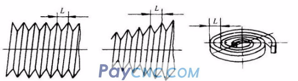
The CNC lathe can process straight threads, tapered threads, and end threads, as shown in the figure. The processing method is divided into single-stroke thread cutting, simple thread cutting cycle and thread cutting compound cycle.
(1) Single stroke thread cutting G32
Instruction format: G32 X(U)____Z(W)____F____
X(U) and Z(W) in the command are the coordinates of the thread end point, and F is the thread lead. The parameters to be determined before using the G32 command are shown in Figure a. The meaning of each parameter is as follows:
L: Thread lead, when machining taper threads, the one with the larger thread lead in the X and Z directions;
α: taper angle of taper thread, if α is zero, it is straight thread;
δ1, δ2: the cut-in amount and cut-out amount. Generally δ1=2~5mm, δ2=(1/4~1/2)δ1.
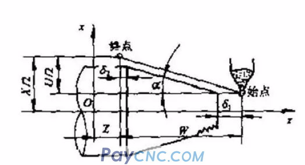
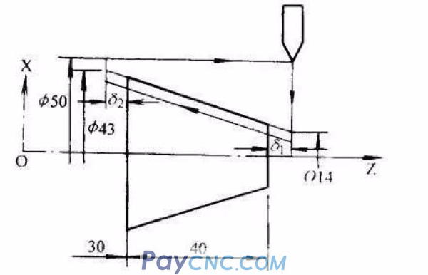
Figure b
Thread processing example: As shown in Figure b, the thread pitch L=3.5mm, the thread height=2mm, the spindle speed N=514r/min, δ1=2mm, δ2=lmm, two turnings, each turning depth is lmm. The processing procedure is:
N0 G50 X50.0 Z70.0 Set the workpiece origin on the left end
N2 S514 T0202 M08 M03 specified spindle speed 514r/min, adjustable thread turning tool
N4 G00 Xl2.0 Z72.0; quickly go to the starting point of thread turning (12.0, 72.0)
N6 G32 X41.0 Z29.0 F3.5; thread turning
N8 G00 X50.0; rapid retraction along the X axis
N10 Z72.0; Quick retreat along Z axis
N12 X10.0; quickly go to the starting point of the second thread turning
N14 G32 X39.0 Z29.0; second thread turning
N16 G00 X50.0; rapid retreat along X axis
N18 G30 U0 W0 M09; reference point return
N20 M30; end of program
(2) Thread cutting cycle command G92
The thread cutting cycle G92 is a simple thread cycle. This command can cut tapered threads and cylindrical threads. The cycle path is basically the same as the single shape fixed cycle described above, except that the subsequent feed amount of F is changed to the pitch value. The instruction format is:
G92 X(U)____Z(W)____R____F____;
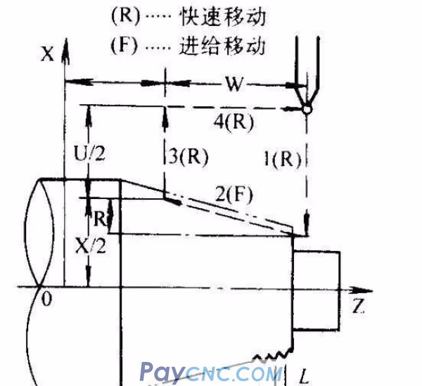
The picture shows the cycle diagram of thread cutting. The tool starts from the cycle starting point A and presses A→B→C→D→A to perform automatic cycle. The broken line in the figure indicates the rapid movement of the tool, and the solid line indicates the movement at the working speed specified by F. X and Z are the coordinate values of the thread end point (point C); U and W are the incremental values from the starting point coordinates to the ending point coordinates; R is the difference between the end point radius of the taper thread and the starting point radius, and the method for determining the positive and negative of the R value is the same as G90 , Cylindrical thread R=0, it can be omitted; F is the pitch value. Thread cutting retraction angle is 45°.
Thread processing example: processing threads as shown in Figure b above. The procedure is:
N0 G50 X50.0 Z70.0; set the workpiece origin on the left end
N2 S514 T0202 M08 M03; specified spindle speed 514r/min, adjusting thread turning tool
N4 G00 X12.0 Z72.0; quickly walk to the starting point of thread turning (12.0, 72.0)
N6 G92 X41.0 Z29.0 R29.0 F3.5; thread turning
N8 X39
N10 G30 U20 W20 M09; reference point return
N12 M30; end of program
(3) Thread cutting multiple cycle command G76
G76 thread cutting multiple cycle instructions are simpler than G32 and G92 instructions. You only need to specify the relevant parameters once in the program, and the threading process is automatically performed. The instruction execution process is shown in the figure below, and the instruction format is as follows:
The format of the G76 thread cutting instruction needs to be defined by two instructions at the same time. The format is:
G76 P(m)(r)(a) Q____R____;
G76 X(U) Z(W) R(i) P(k) Q(Δd) F(L);
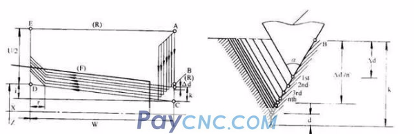
The meaning of the relevant geometric parameters in the formula is shown in the figure, and the definition of each parameter is as follows:
m: number of repetitions of fine turning, from 1-99, the parameter is the modal value.
r: The chamfering value of the thread end. The value of this value can be set between 0.0L and 9.9L. The coefficient should be an integer multiple of 0.1. It is expressed as a two-digit integer between 00 and 99, where L is the pitch. This parameter is the modal quantity.
a: The tool angle can be selected from six angles of 80°, 60°, 55°, 30°, 29° and 0°, which are expressed by two-digit integers. This parameter is the modal quantity.
m, r and a are specified at the same time with address P, for example: m=2, r=1.2L, a=60°, expressed as P021260.
Q: The minimum turning depth is specified by radius programming. Each turning depth in the turning process is (Δd-Δd). When the calculated depth is less than this limit, the turning depth is locked at this value. This parameter is the modal quantity.
R: Finishing allowance, specified by radius programming. This parameter is the modal quantity,
X(U), Z(W): thread end coordinate
i: Thread taper value, specified by radius programming. If R=0, it is a straight thread.
k: thread height, specified by radius programming.
Δd: Depth of the first turning, specified by radius programming.
L: pitch.
In the above two instructions, the value after the Q, R, P address should be expressed without decimal point.
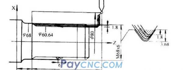
G76 thread turning example: the picture above is a straight thread on the part shaft, the thread height is 3.68mm, the pitch is 6mm, the thread end chamfer is 1.1L, the tool tip angle is 60°, the first turning depth is 1.8mm, The minimum turning depth is 0.1mm. The procedure is:
N16 G76 P011160 Q100 R200;
N18 G76 X60.64 Z25.0 P3680 Q1800 F6.0;
(1) Single stroke thread cutting G32
Instruction format: G32 X(U)____Z(W)____F____
X(U) and Z(W) in the command are the coordinates of the thread end point, and F is the thread lead. The parameters to be determined before using the G32 command are shown in Figure a. The meaning of each parameter is as follows:
L: Thread lead, when machining taper threads, the one with the larger thread lead in the X and Z directions;
α: taper angle of taper thread, if α is zero, it is straight thread;
δ1, δ2: the cut-in amount and cut-out amount. Generally δ1=2~5mm, δ2=(1/4~1/2)δ1.
Figure b
Thread processing example: As shown in Figure b, the thread pitch L=3.5mm, the thread height=2mm, the spindle speed N=514r/min, δ1=2mm, δ2=lmm, two turnings, each turning depth is lmm. The processing procedure is:
N0 G50 X50.0 Z70.0 Set the workpiece origin on the left end
N2 S514 T0202 M08 M03 specified spindle speed 514r/min, adjustable thread turning tool
N4 G00 Xl2.0 Z72.0; quickly go to the starting point of thread turning (12.0, 72.0)
N6 G32 X41.0 Z29.0 F3.5; thread turning
N8 G00 X50.0; rapid retraction along the X axis
N10 Z72.0; Quick retreat along Z axis
N12 X10.0; quickly go to the starting point of the second thread turning
N14 G32 X39.0 Z29.0; second thread turning
N16 G00 X50.0; rapid retreat along X axis
N18 G30 U0 W0 M09; reference point return
N20 M30; end of program
(2) Thread cutting cycle command G92
The thread cutting cycle G92 is a simple thread cycle. This command can cut tapered threads and cylindrical threads. The cycle path is basically the same as the single shape fixed cycle described above, except that the subsequent feed amount of F is changed to the pitch value. The instruction format is:
G92 X(U)____Z(W)____R____F____;
The picture shows the cycle diagram of thread cutting. The tool starts from the cycle starting point A and presses A→B→C→D→A to perform automatic cycle. The broken line in the figure indicates the rapid movement of the tool, and the solid line indicates the movement at the working speed specified by F. X and Z are the coordinate values of the thread end point (point C); U and W are the incremental values from the starting point coordinates to the ending point coordinates; R is the difference between the end point radius of the taper thread and the starting point radius, and the method for determining the positive and negative of the R value is the same as G90 , Cylindrical thread R=0, it can be omitted; F is the pitch value. Thread cutting retraction angle is 45°.
Thread processing example: processing threads as shown in Figure b above. The procedure is:
N0 G50 X50.0 Z70.0; set the workpiece origin on the left end
N2 S514 T0202 M08 M03; specified spindle speed 514r/min, adjusting thread turning tool
N4 G00 X12.0 Z72.0; quickly walk to the starting point of thread turning (12.0, 72.0)
N6 G92 X41.0 Z29.0 R29.0 F3.5; thread turning
N8 X39
N10 G30 U20 W20 M09; reference point return
N12 M30; end of program
(3) Thread cutting multiple cycle command G76
G76 thread cutting multiple cycle instructions are simpler than G32 and G92 instructions. You only need to specify the relevant parameters once in the program, and the threading process is automatically performed. The instruction execution process is shown in the figure below, and the instruction format is as follows:
The format of the G76 thread cutting instruction needs to be defined by two instructions at the same time. The format is:
G76 P(m)(r)(a) Q____R____;
G76 X(U) Z(W) R(i) P(k) Q(Δd) F(L);
The meaning of the relevant geometric parameters in the formula is shown in the figure, and the definition of each parameter is as follows:
m: number of repetitions of fine turning, from 1-99, the parameter is the modal value.
r: The chamfering value of the thread end. The value of this value can be set between 0.0L and 9.9L. The coefficient should be an integer multiple of 0.1. It is expressed as a two-digit integer between 00 and 99, where L is the pitch. This parameter is the modal quantity.
a: The tool angle can be selected from six angles of 80°, 60°, 55°, 30°, 29° and 0°, which are expressed by two-digit integers. This parameter is the modal quantity.
m, r and a are specified at the same time with address P, for example: m=2, r=1.2L, a=60°, expressed as P021260.
Q: The minimum turning depth is specified by radius programming. Each turning depth in the turning process is (Δd-Δd). When the calculated depth is less than this limit, the turning depth is locked at this value. This parameter is the modal quantity.
R: Finishing allowance, specified by radius programming. This parameter is the modal quantity,
X(U), Z(W): thread end coordinate
i: Thread taper value, specified by radius programming. If R=0, it is a straight thread.
k: thread height, specified by radius programming.
Δd: Depth of the first turning, specified by radius programming.
L: pitch.
In the above two instructions, the value after the Q, R, P address should be expressed without decimal point.
G76 thread turning example: the picture above is a straight thread on the part shaft, the thread height is 3.68mm, the pitch is 6mm, the thread end chamfer is 1.1L, the tool tip angle is 60°, the first turning depth is 1.8mm, The minimum turning depth is 0.1mm. The procedure is:
N16 G76 P011160 Q100 R200;
N18 G76 X60.64 Z25.0 P3680 Q1800 F6.0;