USD
USD
Common failures of RS485 communication, solutions and precautions for wiring installation!
Many novices will come into contact with RS485 communication when doing electrical automation engineering. Many novices don’t understand very well. Today we will talk about RS485-related applications. You will find that there is indeed a lot of knowledge in it. Then we will choose some of the usual skills in engineering. The issues considered are for your reference.
01
What is the RS485 bus?
image
Industrial sites often need to collect multi-point data, analog signals or switch signals. Generally, RS485 bus is used. RS-485 adopts half-duplex working mode and supports multi-point data communication. The RS-485 bus network topology generally adopts a bus-type structure with terminal matching. That is, a bus is used to connect each node in series, and ring or star networks are not supported. RS485 has no specific physical shape. According to the actual situation of the project, the interface adopted, RS485 adopts the negative logic of differential signal, +2V~+6V means "0", -6V~-2V means "1".
RS485 has two-wire and four-wire connections. The four-wire system can only realize point-to-point communication, which is rarely used now. Nowadays, the two-wire connection method is mostly used. This wiring method is a bus-type topology. Up to 32 nodes can be connected on the same bus.
According to the 485 bus structure theory, under the premise of an ideal environment, the 485 bus transmission distance can reach 1200 meters. The condition is that the communication wire is high-quality and meets the standard, the baud rate is 9600, and only one 485 device is loaded, so that the communication distance can reach 1200 meters, so the actual and stable communication distance of the 485 bus is usually less than 1200 meters. If there are many load 485 devices, the wire impedance is not up to the standard, the wire diameter is too thin, the converter quality is poor, the equipment lightning protection is complicated, and the baud rate is increased.
02
RS485 cable and transmission distance
image
Ordinary twisted-pair cables can be used in general occasions, and shielded coaxial cables can be used in environments with relatively high requirements. When using the RS485 interface, for a specific transmission line, the maximum cable length allowed for data signal transmission from the RS485 interface to the load is inversely proportional to the baud rate of the signal transmission. This length data is mainly affected by signal distortion and noise. influences.
In theory, the longest transmission distance of RS485 can reach 1200 meters, but the transmission distance in practical applications is shorter than 1200 meters. The specific transmission distance depends on the surrounding environment. In the transmission process, the method of adding relays can be used to amplify the signal. Up to eight relays can be added. That is to say, the maximum transmission distance of RS485 can reach 9.6 kilometers in theory. If long-distance transmission is really needed, optical fiber can be used as the propagation medium, and a photoelectric converter is added at both ends of the transceiver. The transmission distance of multimode fiber is 5-10 kilometers, while the transmission distance of single-mode fiber can be up to 50 kilometers.
03
Precautions for RS485 wiring installation
image
(1) What kind of communication line should be used for 485 bus?
How many devices can be connected to a bus? RVSP shielded twisted pair must be used. The specifications of the shielded twisted pair used are related to the distance of the 485 communication line and the number of connected devices, as shown in the following table. The use of shielded twisted-pair cables helps to reduce and eliminate the distributed capacitance between the two 485 communication lines and the common mode interference generated around the communication lines.
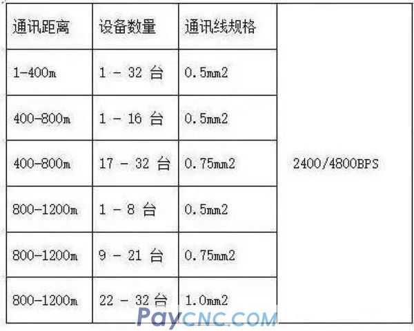
Some people say that the 485 bus can carry 128 devices for communication. In fact, not all 485 converters can be equipped with 128 devices. It should be judged according to the model of the chip in the 485 converter and the model of the 485 device chip, and the load capacity can only be determined according to the chip with a lower index. Generally, there are three levels of 485 chip load capacity-32 units, 128 units and 256 units. In addition, the theoretical nominal rating is often not reached in fact. The longer the communication distance, the higher the baud rate, the thinner the wire diameter, the worse the wire quality, the worse the quality of the converter, and the insufficient power supply of the converter (passive Converter), the stronger the lightning protection, these will reduce the real load quantity. Most engineering companies are accustomed to using Category 5 network cables or over Category 5 network cables as 485 communication lines, which is wrong. This is because:
1. Ordinary network cables have no shielding layer and cannot prevent common mode interference.
2. It is not allowed to use a network cable with a wire diameter that is too thin, which will reduce the transmission distance and reduce the equipment that can be connected. At least 0.4mm square or use a standard network cable.
3. The network cable is a single-strand copper wire, which is easier to break than a multi-core wire.
(2) Why should it be grounded?
The 485 transceiver can work normally when the specified common-mode voltage is between -7V and +12V. If it exceeds this range, the communication will be affected, and the communication interface will be damaged severely. Common-mode interference will increase the above-mentioned common-mode voltage. One of the effective ways to eliminate common-mode interference is to use the shielding layer of the 485 communication line as a ground wire, connect the equipment in the network such as machines, computers, etc., and connect them to the ground reliably from one point.
(3) How should the 485 communication line be routed?
The communication line should be as far away as possible from interference sources such as high-voltage wires, fluorescent lamps, etc. When the communication line cannot be avoided from interference sources such as power lines, the communication line should be perpendicular to the power line, not parallel, and cannot be bundled together, and use high-quality twisted-pair cables. line.
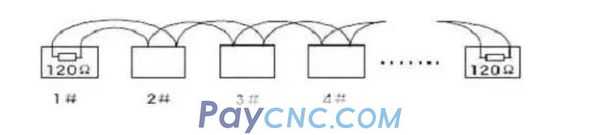
(4) Why should the 485 bus adopt the hand-in-hand structure instead of the star structure?
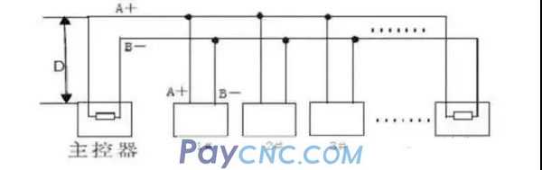
The star structure will produce reflected signals, which will affect the 485 communication. The length of the branch line from the bus to each terminal device should be as short as possible, generally not exceeding 5 meters. If the branch line is not connected to the terminal, there will be reflected signals, which will cause strong interference to the communication. It should be removed. It is best to connect a 120Ω terminal resistor at both ends of the RS485 device.
The handle connection is as shown in the figure:
The star connection is shown in the figure:
(5) Is there a connection point from device to device on the 485 bus?
In the same network system, use the same type of cable to minimize the number of contacts in the line. Ensure that the joints are well welded and wrapped tightly to avoid loosening and oxidation. Ensure a single, continuous signal channel as a bus.
(6) What is common mode interference and differential mode interference?
How to eliminate the interference on the communication line? The 485 communication line is composed of two twisted-pair lines. It transmits signals through the voltage difference between the two communication lines, so it is called differential voltage transmission. Differential mode interference is transmitted between two signal lines and belongs to symmetrical interference. The method to eliminate differential mode interference is to add a bias resistor (matching resistance in the dome camera) to the circuit, and use twisted-pair wires; common mode interference is transmitted between the signal line and the ground, which is asymmetrical interference. Methods to eliminate common mode interference include:
1. Use shielded twisted pair wire and effectively ground it.
2. Where there is a strong electric field, the use of galvanized pipes for shielding should be considered.
3. Keep away from high-voltage wires when wiring, and do not bundle high-voltage power wires and signal wires together.
4. Use linear regulated power supply or high-quality switching power supply (ripple interference is less than 50mV).
(7) Under what circumstances should a terminal resistance be added to the 485 bus?
Generally, there is no need to increase the terminal resistance. Only when the 485 communication distance exceeds 300 meters, the terminal resistance should be added at the beginning and end of the 485 communication. Especially when the number of devices on the 485 bus is small. When the number of equipment is large (such as more than 22). Generally, there is no need to increase the terminal resistance, because the terminal resistance will reduce the load capacity of the 485 bus. The connection method of the 120Ω matching resistance of the dome terminal is as follows: The 120Ω matching resistance of the dome terminal can be connected by the dial switch on the chassis of the dome. ,As shown below. When the dome camera leaves the factory, the 120Ω matching resistance is not connected by default. You can connect the 120Ω matching resistance to the line by turning the 10th bit of the DIP switch to ON. On the contrary, if the 120Ω matching resistance is not connected, just turn the 10th bit to OFF.
(8) Problems in practical applications.
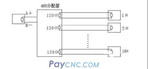
In actual construction use, users often use star connection. At this time, the terminal resistor must be connected to the two devices with the farthest line (as shown in Figure 3, 1# and 15# devices), but because this connection method does not conform to RS485 industry Standard use requirements, so when the distance between each device line is relatively long, it is easy to cause problems such as signal reflection and anti-interference ability, which leads to a decrease in the reliability of the control signal. At this time, the phenomenon is that the dome camera is completely out of control, or it can't stop running on its own, etc.
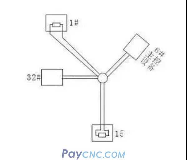
In this case, it is recommended to add an RS485 distributor. This product can effectively convert the star connection to a connection mode that meets the requirements of the RS485 industry standard, thereby avoiding problems and improving communication reliability, as shown in Figure 4.
(9) Recommended cable for maximum transmission distance without relay
1. Ordinary twisted pair shielded cable STP-120Ω (for RS485 & CAN) one pair 20 AWG, the outer diameter of the cable is about 7.7mm. Suitable for indoor, pipeline and general industrial environment. When in use, one end of the shielding layer should be grounded!
2. Ordinary twisted pair shielded cable STP-120Ω (for RS485 & CAN) one pair 18 AWG, the cable outer diameter is about 8.2mm. Suitable for indoor, pipeline and general industrial environment. When in use, one end of the shielding layer should be grounded!
3. Armored twisted-pair shielded cable ASTP-120Ω (for RS485 & CAN) one pair 18 AWG, the outer diameter of the cable is about 12.3mm. It can be used in places with severe interference, frequent rodent damage, and lightning protection and explosion-proof requirements. When in use, it is recommended that both ends of the armor layer be grounded and the innermost shielding end is grounded.
04
RS485 common faults and solutions
image
(1) How to prevent the occurrence of failures?
In order to reduce communication failures, the following suggestions are provided:
● It is recommended that users use and purchase the 485 converter provided by the manufacturer or the 485 converter of the recommended brand specified by the manufacturer;
● The manufacturer will do a lot of testing work for its supporting 485 converter, and will require the 485 converter manufacturer to carry out production and quality testing according to its fixed performance parameters, so it has better compatibility with access control equipment. Don't be greedy to buy a 485 converter from a brand-name manufacturer at a low price.
● Carry out construction strictly in accordance with the 485 bus construction specification to prevent any fluke.
● Use scientific and reserved solutions for 485 bus projects with long lines and heavy loads.
● If the communication distance is too long, such as over 500 meters, it is recommended to use a repeater or 485 HUB to solve it.
● If there are too many loads, such as more than 30 units on a bus, it is recommended to use 485 HUB to solve the problem.
● On-site debugging with complete debugging equipment. For on-site debugging, you must carry a few converters that can connect to long distances and multiple loads, a commonly used computer notebook, a multimeter to test the circuit break, and a few 120 ohm terminal resistors.
(2) The common communication failures with 485 bus structure are as follows?
● No communication, no response.
● You can upload data, but not download data.
● The system prompts that there is interference during communication, or the communication indicator keeps flashing when not communicating.
● Sometimes it can communicate, sometimes it can't communicate, some commands can be communicated, and some commands cannot be communicated.
(3) What are the debugging methods for failure?
Before debugging, make sure that the wiring of the equipment is correct and the construction conforms to the specifications. The following debugging methods can be used according to the problems encountered.
Common land method:
Use a wire or shielded wire to connect the GND ground of all 485 devices, so as to avoid the potential difference between all devices that affects communication.
Terminal resistance method
Connect 120 ohm terminal resistors in parallel to the 485+ and 485- of the last 485 device to improve the communication quality.
Intermediate segmentation method
By disconnecting from the middle, check whether the equipment is overloaded, the communication distance is too long, or the influence of a certain device on the entire communication line, etc.
Individual drawing method
Simply pull a line to the device alone, which can be used to rule out whether the wiring is causing the communication failure.
Replacement converter method
Carry a few converters with you so that you can rule out whether the quality of the converter is affecting the communication quality.
Notebook debugging method
First, make sure that the computer notebook you carry with you is a device with normal communication, and use it to replace the customer's computer for communication. If it is normal, it indicates that the serial port of the customer's computer may be damaged or injured. There are many applications of RS485 in weak current intelligent engineering, and the most common applications are in access control systems, BA systems, intelligent lighting systems, parking lot management systems, etc. With the continuous popularization of digital networks, RS485 is now less and less used in weak current applications.
01
What is the RS485 bus?
image
Industrial sites often need to collect multi-point data, analog signals or switch signals. Generally, RS485 bus is used. RS-485 adopts half-duplex working mode and supports multi-point data communication. The RS-485 bus network topology generally adopts a bus-type structure with terminal matching. That is, a bus is used to connect each node in series, and ring or star networks are not supported. RS485 has no specific physical shape. According to the actual situation of the project, the interface adopted, RS485 adopts the negative logic of differential signal, +2V~+6V means "0", -6V~-2V means "1".
RS485 has two-wire and four-wire connections. The four-wire system can only realize point-to-point communication, which is rarely used now. Nowadays, the two-wire connection method is mostly used. This wiring method is a bus-type topology. Up to 32 nodes can be connected on the same bus.
According to the 485 bus structure theory, under the premise of an ideal environment, the 485 bus transmission distance can reach 1200 meters. The condition is that the communication wire is high-quality and meets the standard, the baud rate is 9600, and only one 485 device is loaded, so that the communication distance can reach 1200 meters, so the actual and stable communication distance of the 485 bus is usually less than 1200 meters. If there are many load 485 devices, the wire impedance is not up to the standard, the wire diameter is too thin, the converter quality is poor, the equipment lightning protection is complicated, and the baud rate is increased.
02
RS485 cable and transmission distance
image
Ordinary twisted-pair cables can be used in general occasions, and shielded coaxial cables can be used in environments with relatively high requirements. When using the RS485 interface, for a specific transmission line, the maximum cable length allowed for data signal transmission from the RS485 interface to the load is inversely proportional to the baud rate of the signal transmission. This length data is mainly affected by signal distortion and noise. influences.
In theory, the longest transmission distance of RS485 can reach 1200 meters, but the transmission distance in practical applications is shorter than 1200 meters. The specific transmission distance depends on the surrounding environment. In the transmission process, the method of adding relays can be used to amplify the signal. Up to eight relays can be added. That is to say, the maximum transmission distance of RS485 can reach 9.6 kilometers in theory. If long-distance transmission is really needed, optical fiber can be used as the propagation medium, and a photoelectric converter is added at both ends of the transceiver. The transmission distance of multimode fiber is 5-10 kilometers, while the transmission distance of single-mode fiber can be up to 50 kilometers.
03
Precautions for RS485 wiring installation
image
(1) What kind of communication line should be used for 485 bus?
How many devices can be connected to a bus? RVSP shielded twisted pair must be used. The specifications of the shielded twisted pair used are related to the distance of the 485 communication line and the number of connected devices, as shown in the following table. The use of shielded twisted-pair cables helps to reduce and eliminate the distributed capacitance between the two 485 communication lines and the common mode interference generated around the communication lines.
Some people say that the 485 bus can carry 128 devices for communication. In fact, not all 485 converters can be equipped with 128 devices. It should be judged according to the model of the chip in the 485 converter and the model of the 485 device chip, and the load capacity can only be determined according to the chip with a lower index. Generally, there are three levels of 485 chip load capacity-32 units, 128 units and 256 units. In addition, the theoretical nominal rating is often not reached in fact. The longer the communication distance, the higher the baud rate, the thinner the wire diameter, the worse the wire quality, the worse the quality of the converter, and the insufficient power supply of the converter (passive Converter), the stronger the lightning protection, these will reduce the real load quantity. Most engineering companies are accustomed to using Category 5 network cables or over Category 5 network cables as 485 communication lines, which is wrong. This is because:
1. Ordinary network cables have no shielding layer and cannot prevent common mode interference.
2. It is not allowed to use a network cable with a wire diameter that is too thin, which will reduce the transmission distance and reduce the equipment that can be connected. At least 0.4mm square or use a standard network cable.
3. The network cable is a single-strand copper wire, which is easier to break than a multi-core wire.
(2) Why should it be grounded?
The 485 transceiver can work normally when the specified common-mode voltage is between -7V and +12V. If it exceeds this range, the communication will be affected, and the communication interface will be damaged severely. Common-mode interference will increase the above-mentioned common-mode voltage. One of the effective ways to eliminate common-mode interference is to use the shielding layer of the 485 communication line as a ground wire, connect the equipment in the network such as machines, computers, etc., and connect them to the ground reliably from one point.
(3) How should the 485 communication line be routed?
The communication line should be as far away as possible from interference sources such as high-voltage wires, fluorescent lamps, etc. When the communication line cannot be avoided from interference sources such as power lines, the communication line should be perpendicular to the power line, not parallel, and cannot be bundled together, and use high-quality twisted-pair cables. line.
(4) Why should the 485 bus adopt the hand-in-hand structure instead of the star structure?
The star structure will produce reflected signals, which will affect the 485 communication. The length of the branch line from the bus to each terminal device should be as short as possible, generally not exceeding 5 meters. If the branch line is not connected to the terminal, there will be reflected signals, which will cause strong interference to the communication. It should be removed. It is best to connect a 120Ω terminal resistor at both ends of the RS485 device.
The handle connection is as shown in the figure:
The star connection is shown in the figure:
(5) Is there a connection point from device to device on the 485 bus?
In the same network system, use the same type of cable to minimize the number of contacts in the line. Ensure that the joints are well welded and wrapped tightly to avoid loosening and oxidation. Ensure a single, continuous signal channel as a bus.
(6) What is common mode interference and differential mode interference?
How to eliminate the interference on the communication line? The 485 communication line is composed of two twisted-pair lines. It transmits signals through the voltage difference between the two communication lines, so it is called differential voltage transmission. Differential mode interference is transmitted between two signal lines and belongs to symmetrical interference. The method to eliminate differential mode interference is to add a bias resistor (matching resistance in the dome camera) to the circuit, and use twisted-pair wires; common mode interference is transmitted between the signal line and the ground, which is asymmetrical interference. Methods to eliminate common mode interference include:
1. Use shielded twisted pair wire and effectively ground it.
2. Where there is a strong electric field, the use of galvanized pipes for shielding should be considered.
3. Keep away from high-voltage wires when wiring, and do not bundle high-voltage power wires and signal wires together.
4. Use linear regulated power supply or high-quality switching power supply (ripple interference is less than 50mV).
(7) Under what circumstances should a terminal resistance be added to the 485 bus?
Generally, there is no need to increase the terminal resistance. Only when the 485 communication distance exceeds 300 meters, the terminal resistance should be added at the beginning and end of the 485 communication. Especially when the number of devices on the 485 bus is small. When the number of equipment is large (such as more than 22). Generally, there is no need to increase the terminal resistance, because the terminal resistance will reduce the load capacity of the 485 bus. The connection method of the 120Ω matching resistance of the dome terminal is as follows: The 120Ω matching resistance of the dome terminal can be connected by the dial switch on the chassis of the dome. ,As shown below. When the dome camera leaves the factory, the 120Ω matching resistance is not connected by default. You can connect the 120Ω matching resistance to the line by turning the 10th bit of the DIP switch to ON. On the contrary, if the 120Ω matching resistance is not connected, just turn the 10th bit to OFF.
(8) Problems in practical applications.
In actual construction use, users often use star connection. At this time, the terminal resistor must be connected to the two devices with the farthest line (as shown in Figure 3, 1# and 15# devices), but because this connection method does not conform to RS485 industry Standard use requirements, so when the distance between each device line is relatively long, it is easy to cause problems such as signal reflection and anti-interference ability, which leads to a decrease in the reliability of the control signal. At this time, the phenomenon is that the dome camera is completely out of control, or it can't stop running on its own, etc.
In this case, it is recommended to add an RS485 distributor. This product can effectively convert the star connection to a connection mode that meets the requirements of the RS485 industry standard, thereby avoiding problems and improving communication reliability, as shown in Figure 4.
(9) Recommended cable for maximum transmission distance without relay
1. Ordinary twisted pair shielded cable STP-120Ω (for RS485 & CAN) one pair 20 AWG, the outer diameter of the cable is about 7.7mm. Suitable for indoor, pipeline and general industrial environment. When in use, one end of the shielding layer should be grounded!
2. Ordinary twisted pair shielded cable STP-120Ω (for RS485 & CAN) one pair 18 AWG, the cable outer diameter is about 8.2mm. Suitable for indoor, pipeline and general industrial environment. When in use, one end of the shielding layer should be grounded!
3. Armored twisted-pair shielded cable ASTP-120Ω (for RS485 & CAN) one pair 18 AWG, the outer diameter of the cable is about 12.3mm. It can be used in places with severe interference, frequent rodent damage, and lightning protection and explosion-proof requirements. When in use, it is recommended that both ends of the armor layer be grounded and the innermost shielding end is grounded.
04
RS485 common faults and solutions
image
(1) How to prevent the occurrence of failures?
In order to reduce communication failures, the following suggestions are provided:
● It is recommended that users use and purchase the 485 converter provided by the manufacturer or the 485 converter of the recommended brand specified by the manufacturer;
● The manufacturer will do a lot of testing work for its supporting 485 converter, and will require the 485 converter manufacturer to carry out production and quality testing according to its fixed performance parameters, so it has better compatibility with access control equipment. Don't be greedy to buy a 485 converter from a brand-name manufacturer at a low price.
● Carry out construction strictly in accordance with the 485 bus construction specification to prevent any fluke.
● Use scientific and reserved solutions for 485 bus projects with long lines and heavy loads.
● If the communication distance is too long, such as over 500 meters, it is recommended to use a repeater or 485 HUB to solve it.
● If there are too many loads, such as more than 30 units on a bus, it is recommended to use 485 HUB to solve the problem.
● On-site debugging with complete debugging equipment. For on-site debugging, you must carry a few converters that can connect to long distances and multiple loads, a commonly used computer notebook, a multimeter to test the circuit break, and a few 120 ohm terminal resistors.
(2) The common communication failures with 485 bus structure are as follows?
● No communication, no response.
● You can upload data, but not download data.
● The system prompts that there is interference during communication, or the communication indicator keeps flashing when not communicating.
● Sometimes it can communicate, sometimes it can't communicate, some commands can be communicated, and some commands cannot be communicated.
(3) What are the debugging methods for failure?
Before debugging, make sure that the wiring of the equipment is correct and the construction conforms to the specifications. The following debugging methods can be used according to the problems encountered.
Common land method:
Use a wire or shielded wire to connect the GND ground of all 485 devices, so as to avoid the potential difference between all devices that affects communication.
Terminal resistance method
Connect 120 ohm terminal resistors in parallel to the 485+ and 485- of the last 485 device to improve the communication quality.
Intermediate segmentation method
By disconnecting from the middle, check whether the equipment is overloaded, the communication distance is too long, or the influence of a certain device on the entire communication line, etc.
Individual drawing method
Simply pull a line to the device alone, which can be used to rule out whether the wiring is causing the communication failure.
Replacement converter method
Carry a few converters with you so that you can rule out whether the quality of the converter is affecting the communication quality.
Notebook debugging method
First, make sure that the computer notebook you carry with you is a device with normal communication, and use it to replace the customer's computer for communication. If it is normal, it indicates that the serial port of the customer's computer may be damaged or injured. There are many applications of RS485 in weak current intelligent engineering, and the most common applications are in access control systems, BA systems, intelligent lighting systems, parking lot management systems, etc. With the continuous popularization of digital networks, RS485 is now less and less used in weak current applications.